4�
� RF Device Data�
� Freescale Semiconductor�
� MRF7S27130HR3 MRF7S27130HSR3�
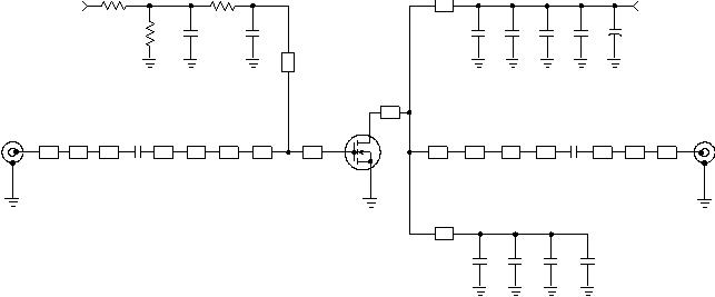
� Figure 1. MRF7S27130HR3(HSR3) Test Circuit Schematic�
� Z11 0.251″�
� x 0.084″�
� Microstrip�
� Z12 0.160″�
� x 0.162″�
� Microstrip�
� Z13 0.566″�
� x 0.084″�
� Microstrip�
� Z14 0.059″�
� x 0.084″�
� Microstrip�
� Z15 0.080″�
� x 0.123″�
� Microstrip�
� Z16 0.583″�
� x 0.084″�
� Microstrip�
� Z17* 0.950″�
� x 0.100″�
� Microstrip�
� Z18, Z19* 0.560″�
� x 0.100″�
� Microstrip�
� PCB Taconic TLX8--0300, 0.030″,�
� εr�
� =2.55�
� * Variable for tuning�
� Z1 0.320″�
� x 0.084″�
� Microstrip�
� Z2 0.380″�
� x 0.240″�
� Microstrip�
� Z3 0.046″�
� x 0.084″�
� Microstrip�
� Z4 0.273″�
� x 0.084″�
� Microstrip�
� Z5 0.360″�
� x 0.600″�
� Microstrip�
� Z6 0.260″�
� x 0.394″�
� Microstrip�
� Z7 0.145″�
� x 0.922″�
� Microstrip�
� Z8 0.455″�
� x 0.922″�
� Microstrip�
� Z9 0.106″�
� x 0.716″�
� Microstrip�
� Z10 0.413″�
� x 0.716″�
� Microstrip�
� VBIAS�
� VSUPPLY�
� RF�
� Z16�
� OUTPUT�
� RF�
� INPUT�
� DUT�
� C2�
� C3�
� R1�
� Z1�
� Z2�
� Z3�
� Z4�
� C1�
� Z10�
� Z5�
� R2�
� Z17�
� Z8�
� Z11�
� Z12�
� Z13�
� Z14�
� Z15�
� Z6�
� C13�
� Z9�
� Z18�
� C4�
� C7�
� C8�
� C12�
� Z19�
� C5�
� C11�
� C9�
� +�
� R3�
� Z7�
� C6�
� C10�
� Table 5. MRF7S27130HR3(HSR3) Test Circuit Component Designations and Values�
� Part�
� Description�
� Part Number�
� Manufacturer�
� C1�
� 2 pF Chip Capacitor�
� ATC100B2R0BT500XT�
� ATC�
� C2, C6, C7, C8, C9, C10, C11�
� 10�
� μF, 50 V Chip Capacitors�
� C5750X5R1H106M�
� TDK�
� C3�
� 3 pF Chip Capacitor�
� ATC100B3R0BT500XT�
� ATC�
� C4, C5�
� 3.6 pF Chip Capacitors�
� ATC100B3R6BT500XT�
� ATC�
� C12�
� 470�
� μF, 63 V Electrolytic Capacitor, Radial�
� EKME630ELL471MK255�
� Multicomp�
� C13�
� 5.6 pF Chip Capacitor�
� ATC100B5R6BT500XT�
� ATC�
� R1, R2�
� 2K?, 1/4 W Chip Resistors�
� CRCW12062001FKEA�
� Vishay�
� R3�
� 10�
� ?, 1/4 W Chip Resistor�
� CRCW120610R1FKEA�
� Vishay�
�  �
�
� � �  �
�
� � �  �
�
� � �  �
�
� � 发布紧急采购,3分钟左右您将得到回复。
相关PDF资料
MRF7S35015HSR5
MOSFET RF N-CH 15W NI-400S-240
MRF7S35120HSR5
MOSFET RF N-CH 120W NI-780S
MRF7S38010HSR5
MOSFET RF N-CH 2W 30V NI-400S
MRF7S38040HSR5
MOSFET RF N-CH 8W 30V NI-400S
MRF7S38075HSR5
MOSFET RF N-CH 12W 30V NI-780S
MRF8P18265HSR6
FET RF N-CH 1840MHZ 30V NI1230S8
MRF8P20100HSR3
FET RF N-CH 2025MHZ 28V NI780H-4
MRF8P20140WHSR3
FET RF LDMOS 28V 500MA NI780S-4
相关代理商/技术参数
MRF7S35015HSR3
功能描述:射频MOSFET电源晶体管 HV7 PULSED 15W NI400S RoHS:否 制造商:Freescale Semiconductor 配置:Single 晶体管极性: 频率:1800 MHz to 2000 MHz 增益:27 dB 输出功率:100 W 汲极/源极击穿电压: 漏极连续电流: 闸/源击穿电压: 最大工作温度: 封装 / 箱体:NI-780-4 封装:Tray
MRF7S35015HSR3_11
制造商:FREESCALE 制造商全称:Freescale Semiconductor, Inc 功能描述:RF Power Field Effect Transistor N--Channel Enhancement--Mode Lateral MOSFET
MRF7S35015HSR5
功能描述:射频MOSFET电源晶体管 HV7 PULSED 15W NI400S RoHS:否 制造商:Freescale Semiconductor 配置:Single 晶体管极性: 频率:1800 MHz to 2000 MHz 增益:27 dB 输出功率:100 W 汲极/源极击穿电压: 漏极连续电流: 闸/源击穿电压: 最大工作温度: 封装 / 箱体:NI-780-4 封装:Tray
MRF7S35120HSR3
功能描述:射频MOSFET电源晶体管 HV7 120W PULSED RoHS:否 制造商:Freescale Semiconductor 配置:Single 晶体管极性: 频率:1800 MHz to 2000 MHz 增益:27 dB 输出功率:100 W 汲极/源极击穿电压: 漏极连续电流: 闸/源击穿电压: 最大工作温度: 封装 / 箱体:NI-780-4 封装:Tray
MRF7S35120HSR5
功能描述:射频MOSFET电源晶体管 HV7 120W PULSED RoHS:否 制造商:Freescale Semiconductor 配置:Single 晶体管极性: 频率:1800 MHz to 2000 MHz 增益:27 dB 输出功率:100 W 汲极/源极击穿电压: 漏极连续电流: 闸/源击穿电压: 最大工作温度: 封装 / 箱体:NI-780-4 封装:Tray
MRF7S38010H
制造商:FREESCALE 制造商全称:Freescale Semiconductor, Inc 功能描述:RF Power Field Effect Transistors N-Channel Enhancement-Mode Lateral MOSFETs
MRF7S38010HR3
功能描述:射频MOSFET电源晶体管 3600MHZ 2W 30V NI400 RoHS:否 制造商:Freescale Semiconductor 配置:Single 晶体管极性: 频率:1800 MHz to 2000 MHz 增益:27 dB 输出功率:100 W 汲极/源极击穿电压: 漏极连续电流: 闸/源击穿电压: 最大工作温度: 封装 / 箱体:NI-780-4 封装:Tray
MRF7S38010HR5
功能描述:射频MOSFET电源晶体管 3600MHZ 2W 30V NI400 RoHS:否 制造商:Freescale Semiconductor 配置:Single 晶体管极性: 频率:1800 MHz to 2000 MHz 增益:27 dB 输出功率:100 W 汲极/源极击穿电压: 漏极连续电流: 闸/源击穿电压: 最大工作温度: 封装 / 箱体:NI-780-4 封装:Tray